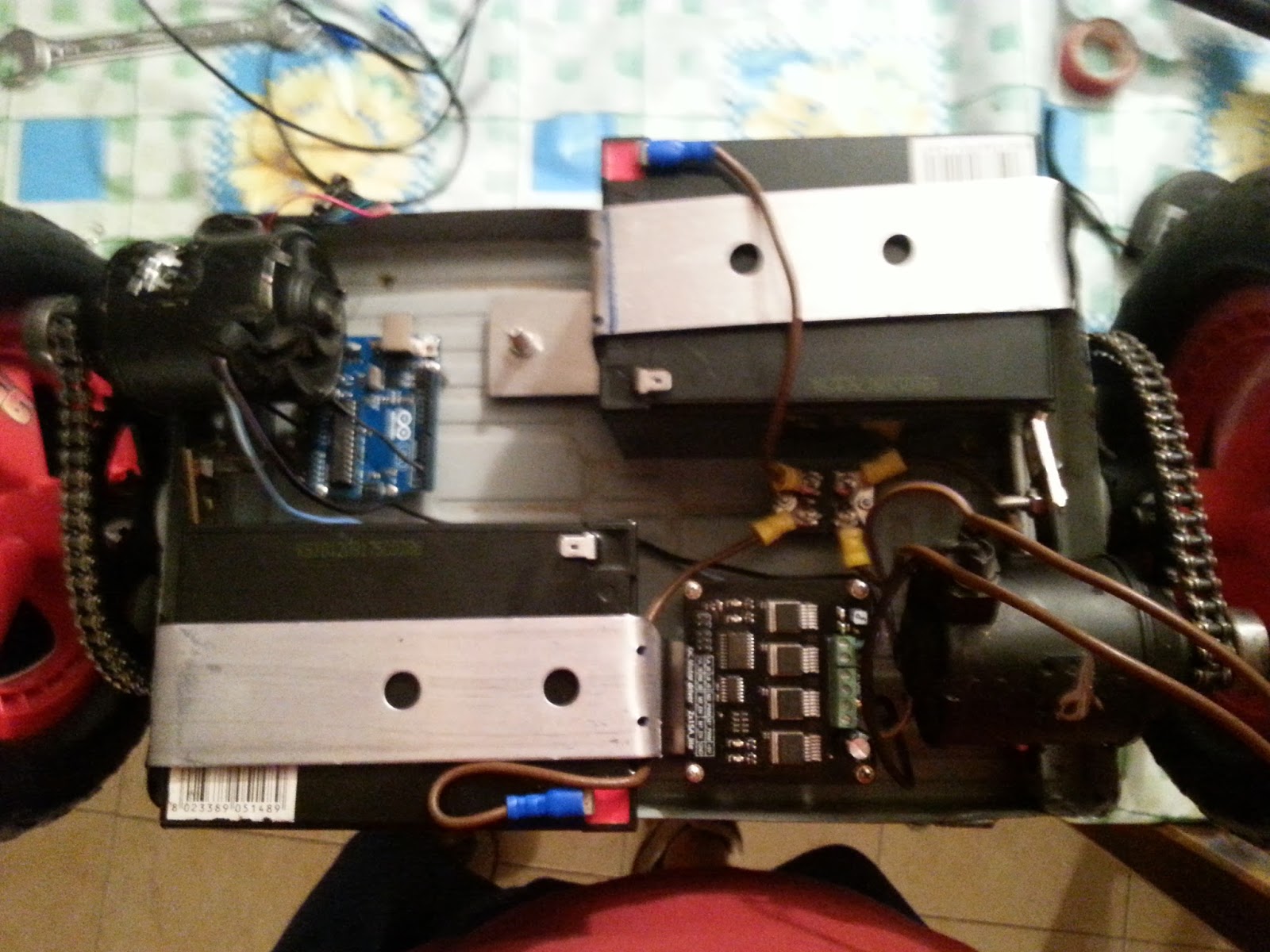
Ora cerchero' di spiegarvi la parte che si e' rilevata la piu' complicata del progetto.
Il software di controllo.
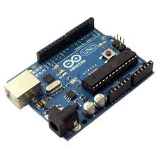
E' stata per me piu' complicata perché con meccanica ed elettronica me la sono cavata con la mia esperienza mentre per quanto riguarda la programmazione di esperienza ne ho poca e quindi ho dovuto cercare aiuto .Per fortuna un mio caro collega ingegnere programmatore ha risolto tutti i miei problemi
Gli sketch del sensore e del motor driver erano gia' fatti e distribuiti dal produttore.
Noi non abbiamo fatto altro che scrivere una parte di sketch per far funzionare le parti dei due sketch che ci servivano.
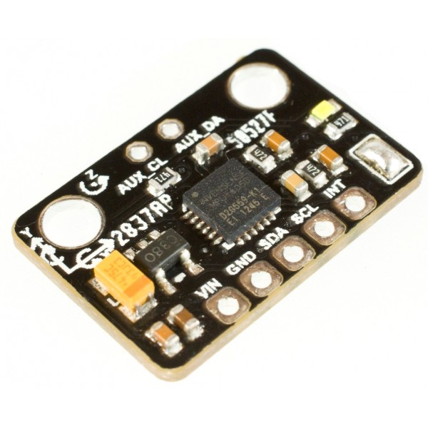
Nello sketch del sensore IMU si ha la possibilità di prendere i dati in uscita in diversi modi,basta fare un uncomment sul metodo che si vuole usare.Inizialmente ho usato il metodo "euler angle" perché pensavo che fosse piu' preciso e inoltre mi dava il dato convertito in gradi.Dopo molti test mi sono accort pero' che il dato dell'inclinazione dell'asse x(per intenderci l'esse parallelo al terreno) non variava solo quando inclinavo il sensore sull'asse X ma anche quando ruotavo il sensore sull'asse Z e quindi quando ruotavo il mezzo per girare i motori impazzivano.Per fortuna c'era un altro metodo per ricavare i dati nello sketch che appunto teneva conto solo del movimento dell'asse X e non degli altri assi chiamato OUTPUT_READABLE_REALACCEL la differenza e' che il dato e' un numero intero e non sono gradi.Pero' incredibile ma vero sono riuscito da solo a fare i calcoli per tarare tutti i valori e modificare lo sketch precedente.
Per capire meglio vi posto gli sketch originali e quello modificato.
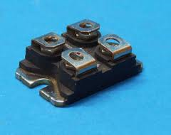
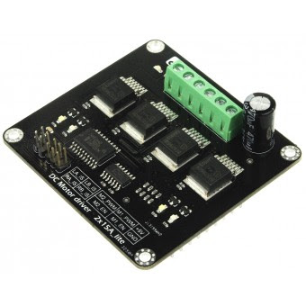
SKETCH MOTOR DRIVER:
int E1 = 5;
int E2 = 6;
int M1 = 4;
int M2 = 7;
int counter=0;
void stop(void)
{
digitalWrite(E1,0);
digitalWrite(M1,LOW);
digitalWrite(E2,0);
digitalWrite(M2,LOW);
}
void advance(char a,char b)
{
analogWrite (E1,a);
digitalWrite(M1,HIGH);
analogWrite (E2,b);
digitalWrite(M2,HIGH);
}
void back_off (char a,char b)
{
analogWrite (E1,a);
digitalWrite(M1,LOW);
analogWrite (E2,b);
digitalWrite(M2,LOW);
}
void turn_L (char a,char b)
{
analogWrite (E1,a);
digitalWrite(M1,LOW);
analogWrite (E2,b);
digitalWrite(M2,HIGH);
}
void turn_R (char a,char b)
{
analogWrite (E1,a);
digitalWrite(M1,HIGH);
analogWrite (E2,b);
digitalWrite(M2,LOW);
}
void current_sense()
{
int val1=digitalRead(2);
int val2=digitalRead(3);
if(val1==HIGH || val2==HIGH){
counter++;
if(counter==3){
counter=0;
Serial.println("Warning");
}
}
}
void setup(void)
{
int i;
for(i=4;i<=7;i++)
pinMode(i, OUTPUT);
Serial.begin(19200);
Serial.println("Run keyboard control");
digitalWrite(E1,LOW);
digitalWrite(E2,LOW);
pinMode(2,INPUT);
pinMode(3,INPUT);
}
void loop(void)
{
if(Serial.available()){
char val = Serial.read();
if(val != -1)
{
switch(val)
{
case 'w':
advance (255,255);
break;
case 's':
back_off (255,255);
break;
case 'a':
turn_L (100,100);
break;
case 'd':
turn_R (100,100);
break;
case 'z':
Serial.println("Hello");
break;
case 'x':
stop();
break;
}
}
else stop();
}
}
In rosso ho evidenziato la parte che ho usato.Tutto il resto non serviva al mio scopo ma e' solo una sequenza per testare il motor driver che ha sviluppato il produttore della scheda.
primo SKETCH usato per il test nel quale ricavavo il dato in gradi poi rivelatosi non adatto.
// I2C device class (I2Cdev) demonstration Arduino sketch for MPU6050 class using DMP (MotionApps v2.0)
// 6/21/2012 by Jeff Rowberg <
jeff@rowberg.net>
// Updates should (hopefully) always be available at
https://github.com/jrowberg/i2cdevlib//
// Changelog:
// 2012-06-21 - added note about Arduino 1.0.1 + Leonardo compatibility error
// 2012-06-20 - improved FIFO overflow handling and simplified read process
// 2012-06-19 - completely rearranged DMP initialization code and simplification
// 2012-06-13 - pull gyro and accel data from FIFO packet instead of reading directly
// 2012-06-09 - fix broken FIFO read sequence and change interrupt detection to RISING
// 2012-06-05 - add gravity-compensated initial reference frame acceleration output
// - add 3D math helper file to DMP6 example sketch
// - add Euler output and Yaw/Pitch/Roll output formats
// 2012-06-04 - remove accel offset clearing for better results (thanks Sungon Lee)
// 2012-06-01 - fixed gyro sensitivity to be 2000 deg/sec instead of 250
// 2012-05-30 - basic DMP initialization working
/* ============================================
I2Cdev device library code is placed under the MIT license
Copyright (c) 2012 Jeff Rowberg
Permission is hereby granted, free of charge, to any person obtaining a copy
of this software and associated documentation files (the "Software"), to deal
in the Software without restriction, including without limitation the rights
to use, copy, modify, merge, publish, distribute, sublicense, and/or sell
copies of the Software, and to permit persons to whom the Software is
furnished to do so, subject to the following conditions:
The above copyright notice and this permission notice shall be included in
all copies or substantial portions of the Software.
THE SOFTWARE IS PROVIDED "AS IS", WITHOUT WARRANTY OF ANY KIND, EXPRESS OR
IMPLIED, INCLUDING BUT NOT LIMITED TO THE WARRANTIES OF MERCHANTABILITY,
FITNESS FOR A PARTICULAR PURPOSE AND NONINFRINGEMENT. IN NO EVENT SHALL THE
AUTHORS OR COPYRIGHT HOLDERS BE LIABLE FOR ANY CLAIM, DAMAGES OR OTHER
LIABILITY, WHETHER IN AN ACTION OF CONTRACT, TORT OR OTHERWISE, ARISING FROM,
OUT OF OR IN CONNECTION WITH THE SOFTWARE OR THE USE OR OTHER DEALINGS IN
THE SOFTWARE.
===============================================
*/
// Arduino Wire library is required if I2Cdev I2CDEV_ARDUINO_WIRE implementation
// is used in I2Cdev.h
#include "Wire.h"
// I2Cdev and MPU6050 must be installed as libraries, or else the .cpp/.h files
// for both classes must be in the include path of your project
#include "I2Cdev.h"
#include "MPU6050_6Axis_MotionApps20.h"
//#include "MPU6050.h" // not necessary if using MotionApps include file
// class default I2C address is 0x68
// specific I2C addresses may be passed as a parameter here
// AD0 low = 0x68 (default for SparkFun breakout and InvenSense evaluation board)
// AD0 high = 0x69
MPU6050 mpu;
/* =========================================================================
NOTE: In addition to connection 3.3v, GND, SDA, and SCL, this sketch
depends on the MPU-6050's INT pin being connected to the Arduino's
external interrupt #0 pin. On the Arduino Uno and Mega 2560, this is
digital I/O pin 2.
* ========================================================================= */
/* =========================================================================
NOTE: Arduino v1.0.1 with the Leonardo board generates a compile error
when using Serial.write(buf, len). The Teapot output uses this method.
The solution requires a modification to the Arduino USBAPI.h file, which
is fortunately simple, but annoying. This will be fixed in the next IDE
release. For more info, see these links:
http://arduino.cc/forum/index.php/topic,109987.0.html http://code.google.com/p/arduino/issues/detail?id=958 * ========================================================================= */
// uncomment "OUTPUT_READABLE_QUATERNION" if you want to see the actual
// quaternion components in a [w, x, y, z] format (not best for parsing
// on a remote host such as Processing or something though)
//#define OUTPUT_READABLE_QUATERNION
// uncomment "OUTPUT_READABLE_EULER" if you want to see Euler angles
// (in degrees) calculated from the quaternions coming from the FIFO.
// Note that Euler angles suffer from gimbal lock (for more info, see
//
http://en.wikipedia.org/wiki/Gimbal_lock)
#define OUTPUT_READABLE_EULER
// uncomment "OUTPUT_READABLE_YAWPITCHROLL" if you want to see the yaw/
// pitch/roll angles (in degrees) calculated from the quaternions coming
// from the FIFO. Note this also requires gravity vector calculations.
// Also note that yaw/pitch/roll angles suffer from gimbal lock (for
// more info, see:
http://en.wikipedia.org/wiki/Gimbal_lock)
//#define OUTPUT_READABLE_YAWPITCHROLL
// uncomment "OUTPUT_READABLE_REALACCEL" if you want to see acceleration
// components with gravity removed. This acceleration reference frame is
// not compensated for orientation, so +X is always +X according to the
// sensor, just without the effects of gravity. If you want acceleration
// compensated for orientation, us OUTPUT_READABLE_WORLDACCEL instead.
//#define OUTPUT_READABLE_REALACCEL
// uncomment "OUTPUT_READABLE_WORLDACCEL" if you want to see acceleration
// components with gravity removed and adjusted for the world frame of
// reference (yaw is relative to initial orientation, since no magnetometer
// is present in this case). Could be quite handy in some cases.
//#define OUTPUT_READABLE_WORLDACCEL
// uncomment "OUTPUT_TEAPOT" if you want output that matches the
// format used for the InvenSense teapot demo
//#define OUTPUT_TEAPOT
#define LED_PIN 13 // (Arduino is 13, Teensy is 11, Teensy++ is 6)
bool blinkState = false;
// MPU control/status vars
bool dmpReady = false; // set true if DMP init was successful
uint8_t mpuIntStatus; // holds actual interrupt status byte from MPU
uint8_t devStatus; // return status after each device operation (0 = success, !0 = error)
uint16_t packetSize; // expected DMP packet size (default is 42 bytes)
uint16_t fifoCount; // count of all bytes currently in FIFO
uint8_t fifoBuffer[64]; // FIFO storage buffer
// orientation/motion vars
Quaternion q; // [w, x, y, z] quaternion container
VectorInt16 aa; // [x, y, z] accel sensor measurements
VectorInt16 aaReal; // [x, y, z] gravity-free accel sensor measurements
VectorInt16 aaWorld; // [x, y, z] world-frame accel sensor measurements
VectorFloat gravity; // [x, y, z] gravity vector
float euler[3]; // [psi, theta, phi] Euler angle container
float ypr[3]; // [yaw, pitch, roll] yaw/pitch/roll container and gravity vector
// packet structure for InvenSense teapot demo
uint8_t teapotPacket[14] = { '$', 0x02, 0,0, 0,0, 0,0, 0,0, 0x00, 0x00, '\r', '\n' };
int E1 = 5; //M1 Speed Control
int E2 = 6; //M2 Speed Control
int M1 = 4; //M1 Direction Control
int M2 = 7; //M1 Direction Control
int v = 0;
char vel = 0;
unsigned int delay_counter=0;
#define NUM_ELEM_MEAN 20
float lettura[NUM_ELEM_MEAN];
int attuale = 0;
float media = 0;
// ================================================================
// === INTERRUPT DETECTION ROUTINE ===
// ================================================================
volatile bool mpuInterrupt = false; // indicates whether MPU interrupt pin has gone high
void dmpDataReady() {
mpuInterrupt = true;
}
// ================================================================
// === INITIAL SETUP ===
// ================================================================
void setup() {
// join I2C bus (I2Cdev library doesn't do this automatically)
Wire.begin();
// initialize serial communication
// (115200 chosen because it is required for Teapot Demo output, but it's
// really up to you depending on your project)
Serial.begin(115200);
while (!Serial); // wait for Leonardo enumeration, others continue immediately
// NOTE: 8MHz or slower host processors, like the Teensy @ 3.3v or Ardunio
// Pro Mini running at 3.3v, cannot handle this baud rate reliably due to
// the baud timing being too misaligned with processor ticks. You must use
// 38400 or slower in these cases, or use some kind of external separate
// crystal solution for the UART timer.
// initialize device
Serial.println(F("Initializing I2C devices..."));
mpu.initialize();
// verify connection
Serial.println(F("Testing device connections..."));
Serial.println(mpu.testConnection() ? F("MPU6050 connection successful") : F("MPU6050 connection failed"));
// wait for ready
Serial.println(F("\nSend any character to begin DMP programming and demo: "));
while (Serial.available() && Serial.read()); // empty buffer
while (!Serial.available()); // wait for data
while (Serial.available() && Serial.read()); // empty buffer again
// load and configure the DMP
Serial.println(F("Initializing DMP..."));
devStatus = mpu.dmpInitialize();
// make sure it worked (returns 0 if so)
if (devStatus == 0) {
// turn on the DMP, now that it's ready
Serial.println(F("Enabling DMP..."));
mpu.setDMPEnabled(true);
// enable Arduino interrupt detection
Serial.println(F("Enabling interrupt detection (Arduino external interrupt 0)..."));
attachInterrupt(0, dmpDataReady, RISING);
mpuIntStatus = mpu.getIntStatus();
// set our DMP Ready flag so the main loop() function knows it's okay to use it
Serial.println(F("DMP ready! Waiting for first interrupt..."));
dmpReady = true;
// get expected DMP packet size for later comparison
packetSize = mpu.dmpGetFIFOPacketSize();
} else {
// ERROR!
// 1 = initial memory load failed
// 2 = DMP configuration updates failed
// (if it's going to break, usually the code will be 1)
Serial.print(F("DMP Initialization failed (code "));
Serial.print(devStatus);
Serial.println(F(")"));
}
// configure LED for output
pinMode(LED_PIN, OUTPUT);
int i;
for(i=4;i<=7;i++)
pinMode(i, OUTPUT);
Serial.begin(115200); //Set Baud Rate
Serial.println("Run keyboard control");
digitalWrite(E1,LOW);
digitalWrite(E2,LOW);
pinMode(2,INPUT);
pinMode(3,INPUT);
}
// ================================================================
// === MAIN PROGRAM LOOP ===
// ================================================================
void loop() {
// if programming failed, don't try to do anything
if (!dmpReady) return;
// wait for MPU interrupt or extra packet(s) available
while (!mpuInterrupt && fifoCount < packetSize) {
// other program behavior stuff here
// .
// .
// .
// if you are really paranoid you can frequently test in between other
// stuff to see if mpuInterrupt is true, and if so, "break;" from the
// while() loop to immediately process the MPU data
// .
// .
// .
}
// reset interrupt flag and get INT_STATUS byte
mpuInterrupt = false;
mpuIntStatus = mpu.getIntStatus();
// get current FIFO count
fifoCount = mpu.getFIFOCount();
// check for overflow (this should never happen unless our code is too inefficient)
if ((mpuIntStatus & 0x10) || fifoCount == 1024) {
// reset so we can continue cleanly
mpu.resetFIFO();
Serial.println(F("FIFO overflow!"));
// otherwise, check for DMP data ready interrupt (this should happen frequently)
} else if (mpuIntStatus & 0x02) {
// wait for correct available data length, should be a VERY short wait
while (fifoCount < packetSize) fifoCount = mpu.getFIFOCount();
// read a packet from FIFO
mpu.getFIFOBytes(fifoBuffer, packetSize);
// track FIFO count here in case there is > 1 packet available
// (this lets us immediately read more without waiting for an interrupt)
fifoCount -= packetSize;
#ifdef OUTPUT_READABLE_QUATERNION
// display quaternion values in easy matrix form: w x y z
mpu.dmpGetQuaternion(&q, fifoBuffer);
Serial.print("quat\t");
Serial.print(q.w);
Serial.print("\t");
Serial.print(q.x);
Serial.print("\t");
Serial.print(q.y);
Serial.print("\t");
Serial.println(q.z);
#endif
#ifdef OUTPUT_READABLE_EULER
// display Euler angles in degrees
mpu.dmpGetQuaternion(&q, fifoBuffer);
mpu.dmpGetEuler(euler, &q);
Serial.print("euler\t");
Serial.print(euler[0] * 180/M_PI);
// Serial.print("\t");
// Serial.print(euler[1] * 180/M_PI);
// Serial.print("\t");
// Serial.println(euler[2] * 180/M_PI);
lettura[attuale++] = euler[0]*180/M_PI;
if (attuale > (NUM_ELEM_MEAN - 1) ) {
attuale = 0;
}
media = 0;
for(int index=0;index<NUM_ELEM_MEAN;index++) {
media += lettura[index];
}
media = media / NUM_ELEM_MEAN;
//NEW CODE
if (delay_counter < 200) {
delay_counter++;
} else {
v = (90. + media)*(255./30.);
if (v == 0) {
//fermo
vel = 0;
analogWrite (E1,0);
digitalWrite(M1,LOW);
analogWrite (E2,0);
digitalWrite(M2,LOW);
} else if (v > 0) {
//avanti
vel = v;
analogWrite (E1,vel);
digitalWrite(M1,HIGH);
analogWrite (E2,vel);
digitalWrite(M2,HIGH);
} else {//v < 0
//in dietro
vel = -v;
analogWrite (E1,vel);
digitalWrite(M1,LOW);
analogWrite (E2,vel);
digitalWrite(M2,LOW);
}
} #endif
#ifdef OUTPUT_READABLE_YAWPITCHROLL
// display Euler angles in degrees
mpu.dmpGetQuaternion(&q, fifoBuffer);
mpu.dmpGetGravity(&gravity, &q);
mpu.dmpGetYawPitchRoll(ypr, &q, &gravity);
Serial.print("ypr\t");
Serial.print(ypr[0] * 180/M_PI);
Serial.print("\t");
Serial.print(ypr[1] * 180/M_PI);
Serial.print("\t");
Serial.println(ypr[2] * 180/M_PI);
#endif
#ifdef OUTPUT_READABLE_REALACCEL
// display real acceleration, adjusted to remove gravity
mpu.dmpGetQuaternion(&q, fifoBuffer);
mpu.dmpGetAccel(&aa, fifoBuffer);
mpu.dmpGetGravity(&gravity, &q);
mpu.dmpGetLinearAccel(&aaReal, &aa, &gravity);
Serial.print("areal\t");
Serial.print(aaReal.x);
Serial.print("\t");
Serial.print(aaReal.y);
Serial.print("\t");
Serial.println(aaReal.z);
#endif
#ifdef OUTPUT_READABLE_WORLDACCEL
// display initial world-frame acceleration, adjusted to remove gravity
// and rotated based on known orientation from quaternion
mpu.dmpGetQuaternion(&q, fifoBuffer);
mpu.dmpGetAccel(&aa, fifoBuffer);
mpu.dmpGetGravity(&gravity, &q);
mpu.dmpGetLinearAccel(&aaReal, &aa, &gravity);
mpu.dmpGetLinearAccelInWorld(&aaWorld, &aaReal, &q);
Serial.print("aworld\t");
Serial.print(aaWorld.x);
Serial.print("\t");
Serial.print(aaWorld.y);
Serial.print("\t");
Serial.println(aaWorld.z);
#endif
#ifdef OUTPUT_TEAPOT
// display quaternion values in InvenSense Teapot demo format:
teapotPacket[2] = fifoBuffer[0];
teapotPacket[3] = fifoBuffer[1];
teapotPacket[4] = fifoBuffer[4];
teapotPacket[5] = fifoBuffer[5];
teapotPacket[6] = fifoBuffer[8];
teapotPacket[7] = fifoBuffer[9];
teapotPacket[8] = fifoBuffer[12];
teapotPacket[9] = fifoBuffer[13];
Serial.write(teapotPacket, 14);
teapotPacket[11]++; // packetCount, loops at 0xFF on purpose
#endif
// blink LED to indicate activity
blinkState = !blinkState;
digitalWrite(LED_PIN, blinkState);
}
}
In verde la parte di codice che genera il dato in gradi.
In rosso la parte di codice creata dal collega ing. A.D.C.(Altri ringraziamenti doverosi).
Mi sa che vi ho messo un po' in confusione con tutte queste righe di codice:-)
Nel prossimo post mettero' il codice definitivo modificato da me.


